

Related topics:
Flow direction of Valve – Part 1 (CHECK VALVE)
Flow direction of Valve – Part 2 (BALL VALVE)
Flow direction of Valve – Part 4 (GLOBE VALVE) continue
Flow direction of Valve – Part 5 (BUTTERFLY VALVE)
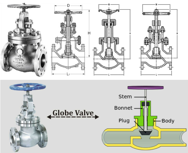
- The globe valve is used for throttling flow control. Shut off is accomplished by moving the disc against the flow stream rather than across it as in the case with a gate valve. The flow pattern through a globe valve involves changes in direction, resulting in greater resistance to flow, causing high pressure drop. The globe valve is an excellent valve to use for on-off service, but is highly suited for frequent cycling and control of fluids anywhere in amount or volume between the open and closed positions.
- The globe valve must be installed in the proper relation to the media flow as indicated by the flow direction arrow marked on the valve body. This valve is considered uni-directional and must be installed with the pressure side or inlet under the seat.
- Cast steel globe valves are highly efficient for services requiring frequent operation and throttling when pressure drop across the valve is about 20% of inlet pressure. Closer throttling, creating higher pressure drops ( exceed 20% ) may cause cavitation or excessive velocities which could cause high noise levels, vibration and possible damage to the valve or adjacent piping. Globe valves can be equipped with optional operators and are available with a variety of trims to match service requirements.
Globe valves are supplied as standard with contour or spherical type plugs and are classified as quick opening on flow curves.

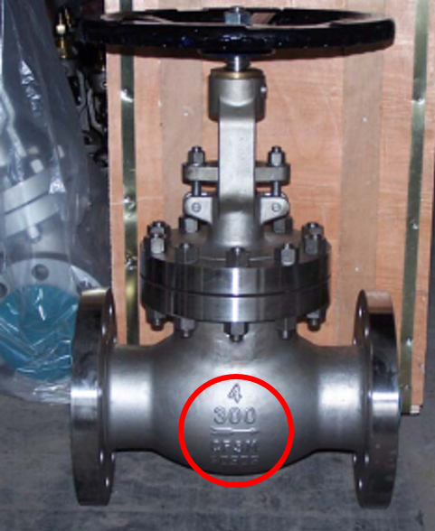
4. Globe valves are created with a disk that translates against a seat. The flow fluid is usually directed up through the seat and around the disk. Most large globe valves have direction arrow embossed on the body casting to show direction of flow. Globe Valves are available in a lot of different options, and it can be a challenge to recognize Globe Valves from a Gate Valves from the outside design only. As mentioned under Gate Valves description there should be an arrow on the Globe Valves body. This arrow is grinded off on Gate Valves body. This arrow also defines the flow direction of the Globe Valves.
5. Body Construction:
Globe valves can be arranged so that the disk closes against or in the same direction of fluid flow. When the disk closes against the direction of flow, the kinetic energy of the fluid impedes closing but aids opening of the valve. When the disk closes in the same direction of flow, the kinetic energy of the fluid aids closing but impedes opening. This characteristic is preferableto other designs when quick-acting stop valves are necessary. Globe valves also have drawbacks. The most evident shortcoming of the simple globe valve isthe high head loss from two or more right angle turns of flowing fluid. Obstructions and discontinuities in the flowpath lead to head loss. In a large high pressure line, the fluid dynamic effects from pulsations, impacts, and pressure drops can damage trim, stem packing, andactuators. In addition, large valve sizes require considerable power to operate and are especially noisy in high pressure applications. Other drawbacks of globe valves are the large openings necessary for disk assembly, heavier weight than other valves of the same flow rating, and the cantilevered mounting of the disk to the stem.
Due to the angles in the globe valve body there is a high level of head loss. Head loss is the measure of reduction in the total head of liquid as it moves through the system. Total head loss can be calculated by summing the elevation head, velocity head and pressure head. While head loss is unavoidable in fluid systems, it is increased by obstructions and discontinuities in the flow path such as the S shape of the globe valve design. The body and flow pipes are rounded and smooth to provide system flow without creating turbulence or noise. To avoid creating additional pressure losses at high velocity the pipes should be a constant area. Globe valves are available in three main body types (although custom designs are available as well): angle design, Y-shaped, and Z- shaped.
- Z-shaped ( T pattern body also ):
The simplest design and most common for water applications is the Z-body. The Z-bodyis illustrated in Figure 9. For this body design, the Z-shaped diaphragm or partitionacross the globular body contains the seat. The horizontal setting of the seat allows thestem and disk to travel at right angles to the pipe axis. The stem passes through thebonnet which is attached to a large opening at the top of the valve body. This providesa symmetrical form that simplifies manufacture, installation, and repair. As shown in Figure 9, the globe valve disk can be totally removed from the flowpath or it can completely close the flowpath. The essential principle of globe valve operation is the perpendicular movement of the disk away from the seat. This causes the annular space between the disk and seat ring to gradually close as the valve is closed. This characteristic gives the globe valve good throttling ability, which permits its use in regulating flow. Therefore, the globe valve may be used for both stopping and starting fluid flowand for regulating flow. When compared to a gate valve, a globe valve generally yields much less seat leakage. This is because the disk-to-seatring contact is more at right angles, which permits the force of closing to tightly seat the disk.

- Y-Body design:
Figure 10 illustrates a typical Y-body globe valve. This design is a remedy for the high pressure drop inherent in globe valves. The seat and stem areangled at approximately 45. The angle yields a straighter flowpath (at full opening) and provides the stem, bonnet, and packing a relatively pressure-resistant envelope. Y-body globe valves are best suited for high pressure and other severe services. In small sizes for intermittent flows, the pressure loss may not be as important as the other considerations favoring the Y-body design. Hence, the flow passage of small Y-body globe valves is not as carefully streamlined as that for larger valves.

- Angle valve design:
The angle body globe valve design, illustrated in Figure 11, is a simple modification of the basic globe valve. Having ends at right angles, the diaphragm can be a simple flat plate. Fluid is able to flow through with onlya single 90 turn and discharge downward more symmetrically than the discharge from an ordinary globe. A particular advantage ofthe angle body design is that it can functionas both a valve and a piping elbow. For moderate conditions of pressure,temperature, and flow, the angle valve closely resembles the ordinary globe. The anglevalve’s discharge conditions are favorable with respect to fluid dynamics and erosion.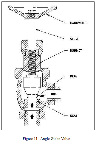
Globe Valve Direction of Flow:
-For low temperature applications, globe and angle valves are ordinarily installed so that pressureis under the disk. This promotes easy operation, helps protect the packing, and eliminates acertain amount of erosive action to the seat and disk faces.
-For high temperature steam service, globe valves are installed so that pressure is above the disk. Otherwise, the stem will contract upon cooling and tend to lift the disk off the seat ( and leaking ).
To Solving Cavitation Damages in globe valves: see Flow direction of Valve – Part 4 (GLOBE VALVE) continue.

Thanks for pointing out that globe valves will usually have an arrow embossed on the body casting to show you which way fluid will flow through them. My husband and I are working on a plumbing project that requires a few globe valves, so I appreciate the tip on how to easily determine flow direction. I learned a lot about valves and their flow directions, so thanks for sharing!
LikeLike
can be use control valve globe type with bypass in both directions?
LikeLike
Thanks for the great article.. I want to understand what damages can happen if gas flow through globe valve in reverse direction? could you help me in this regard..
LikeLike
From which direction we pressurize Globe Valve please clear from Arrow or opposite..
Thank you
LikeLike