

In this chapter, i’d like to introduce about the most common device used for measuring flow rate – Orifice Plate.
Visit: Shipbuilding Knowledge A-Z for more free topics on shipbuilding
or Mechanical and Piping Advanced Knowledge in O&G EPCIC for Mechanical and Piping
Basic Principle of Orifice Meter
When an orifice plate is placed in a pipe carrying the fluid whose rate of flow is to be measured, the orifice plate causes a pressure drop which varies with the flow rate. This pressure drop is measured using a differential pressure sensor and when calibrated this pressure drop becomes a measure flow rate (base on Bernoulli’s Law)

In fluid flow, friction loss (or skin friction) is the loss of pressure or “head” (named HEAD LOSS/ PRESSURE PERMANENT LOSS)that occurs in pipe or duct flow due to the effect of the fluid’s viscosity near the surface of the pipe or duct – This is one of Disadvantage of orifice plate on Piping system.
But the problem is the turbulent of flow near by the orifice will make less accuracy of the Pressure drop sensors, hence we get wrong flow rate calculation.
It called “Flange Tap positions”
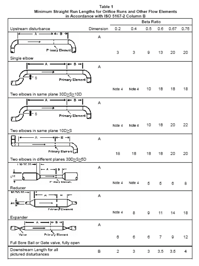
Several standards exist for pressure tap locations. Ideally, the upstream pressure tap will detect fluid pressure at a point of minimum velocity, and the downstream tap will detect pressure at the “vena contracta” (maximum velocity). In reality, this ideal is never perfectly achieved. An overview of the most popular tap locations for orifice plates is shown in the following illustration:

FLANGE TAP (2″ and over)
The most common are flange taps for pipe ( They are located 1 inch from the upstream face of orifice plate and 1 inch from downstream face. They are used for all standard orifice configurations.)
VENA-CONTRACTA TAP (Greater than 6″, for plant measurement where the flows are relatively constant and plates are not changed)
Vena contracta taps offer the greatest differential pressure for any given flow rate, but require precise calculations to properly locate the downstream tap position.
(Vena-Contracta Taps are located 1 pipe diameter upstream of orifice plate and at the point of minimum pressure downstream, this point is called the vena-contracta. This point varies with Beta ratio.)
RADIUS TAP (not commonly used)
Radius Taps are located 1 pipe diameter upstream of orifice plate and one half pipe diameter downstream of orifice plate.
CORNER TAP (less than 2″)
Corner Taps are used for honed meter runs like an integral orifice. They are located immediately adjacent to plate faces both upstream and downstream. Corner taps must be used on small pipe diameters where the vena-contracta is so close to the downstream face of the orifice plate that a downstream flange tap would sense pressure in the highly turbulent region (too far downstream). Corner taps obviously require distinctive (i.e. expensive) flange fittings, which is why they tend to be used only when necessary.
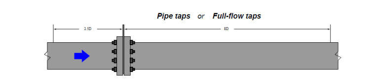
PIPE TAP: (used for unstable flow pipeline as the measurement will not be affected by the flow rate and turbulent at downstream)
Pipe Taps are located two and two and a half ~ (2.5) pipe diameters upstream of orifice plate and eight (8) pipe diameters downstream of orifice plate this puts the downstream tap at the point of maximum pressure recovery.
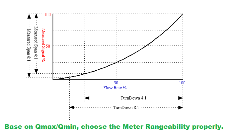
TURNDOWN RATIO OR METER RANGE-ABILITY
In flow measurement, the turndown ratio indicates the range of flow that a flow meter is able to measure with acceptable accuracy. It is also known as rangeability. It is important when choosing a flow meter technology for a specific application. If a gas flow to be measured is expected to vary between 100,000 m³ per day and 1,000,000 m³ per day, the specific application has a turndown ratio of at 10:1. Therefore the meter requires a turndown ratio of at least 10:1. For example: if the meter had an advertised maximum flow of 2,000,000 m³ per day then the required turndown ratio would be 20:1, hence it can read the 100,000 m³.
Note: The Orifice Turndown ratio around 3:1 to 6:1

One thought on “FLOW METER AND ORIFICE PLATE”