
")
There’re some confusing fluid mechanic principles, you may understand it during learning individually. Meanwhile, it’s real difficult and daunting to gather and compile all the theories to design a reasonable pump configuration as the demand.
In this post, we’ll break down the anatomy of all concept through the centrifugal pump curve (Characteristic curves).
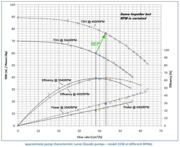
The pump characteristic curve shows the performance of a pump.
It usually shows TDH-Total dynamic Head, Power, Efficiency and NPSHr plotted over Flow rate at a given RPM.
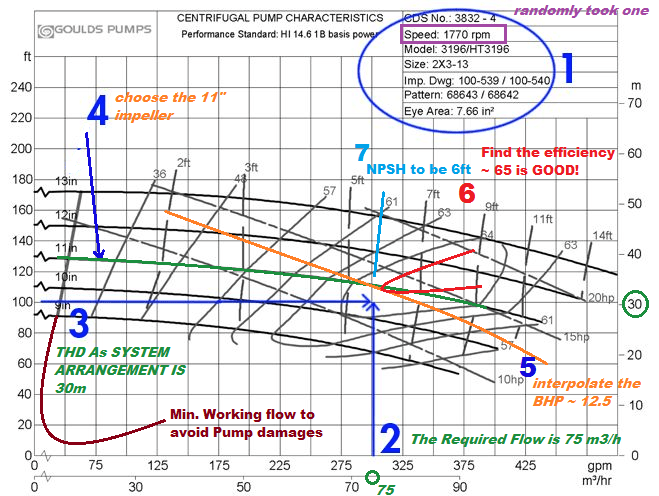
In these diagrams you can estimate pump behavior at constant speeds and a range of impeller diameters. Constant horsepower, efficiency, and NPSHr lines are plotted over the various head curves.

In above example, we assume that we have this pump with an impeller diameter of 7” operating at 3540RPM and a flow rate of 48m³/h. Therefore we can read from the diagram the pump’s current efficiency, head, required power as well as the NPSHr. In this case, our operating point is almost the pump’s B.E.P – Best efficiency point and we get THD of 60m, an efficiency of about 61%, required power of 13Hp and a NPSHr of 9ft
1- Total dynamic head (TDH)
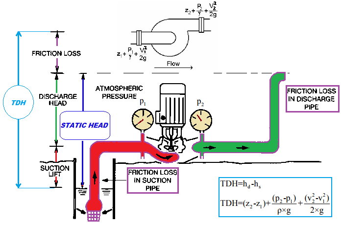
Total dynamic discharge (suction) head is practically the pressure read from a gauge at the discharge (suction) flange converted to length units and corrected to the pump centre line elevation and plus the velocity head at the point of the gauge.
Note: Only P2, we can’t calculate the Head – Refer to Pump Head vs Discharge Pressure
Mathematically it is the sum of static discharge (suction) head and total friction head in the discharge (suction) line.
TDH is the primary design information, can be calculated in accordance with the system arrangement and piping layout. (The friction loss will be calculated base on experience – 30-50% of static head or mathematically).
2- Flow rate (Q)
(Volumetric) Flow rate is the volume of fluid passing through the pump per unit of time. It is calculated as area (A) times fluid velocity (v) as (Q=A.v). It depends on the impeller geometry and RPM. An impeller is designed for a maximized flow rate at a specific speed depending on its diameter. This is called the point of best efficiency. (B.E.P)
The Green line as called as Pump Performance curve at specify RPM & Impeller size.
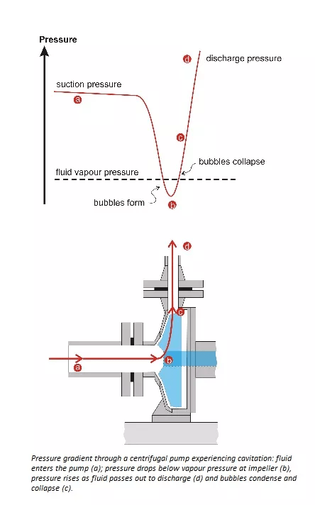
3- Net positive suction head (NPSH)

A liquid can not be sucked inside the pump. Liquid has to be pushed inside the suction pipe. For a liquid to be pushed into a suction pipe some external energy, force or head is required. Atm. provides this head on the free surface of liquid from which the pump draws the liquid.
NPSH required (NPSHR) is the total suction head required to prevent the fluid from vaporising at the lowest pressure point of the pump. NPSHR is a function of pump design as the pressure at the impeller decreases by accelerating the fluid along the impeller. There are also pressure losses due to shock and turbulence as the fluid strikes the impeller. To overcome all these pressure drops in the pump and maintain the fluid above vapour pressure a certain positive suction head is required.
In practice a safety value of 0,5m will be added (+) as optimizing the NPSHR
So if the pressure is low enough it is possible to see this effect is known as cavitations and should necessarily be avoided !!!.
To increase the NPSH consider the following:
- Increase the suction pipe work size to give a fluid velocity of about 1 m/sec or 3 ft/sec
- Redesign the suction pipe work to eliminate bends, valves and fittings where possible.
- Raise the height of the fluid container.
- Pressurized the fluid container, but ensure that the pressure in the container is maintained as the fluid level is lowered
4- Impeller Trim
To accommodate different performance points, centrifugal pumps have the capability of trimming impellers. By reducing impeller size, the pump can be limited to your specific performance requirement. The impeller diameters are listed on the left side of the curve and the performance for each trim is shown across as a bold line.
5- Power and Efficiency
The work performed by a pump is a function of THD, flow rate and the specific gravity of the fluid. Pump input (Pi) or brake horse power (BHP) is the actual power delivered to the pump shaft. Pump output (Po) or hydraulic horse power (WHP) is the energy delivered to the fluid per time unit . Due to mechanical and hydraulic losses in the pump, Phydr is always smaller than P. Therefore efficiency is defined as Po divided by Pi.


1 BHP = 0.75kW
PUMP SELECTION GUIDES:
There’re two common way to approach the reasonable pump as per the demand. One is from Fix RPM but the impeller size is variate, the other is revert as Fix the impeller size ( due to the pump location and working condition ) but RPM be variate.
For easy understand, the first solution will be explained as below:
For the rest:

3 thoughts on “CENTRIFUGAL PUMP (Advanced)”