
")
We continue with remain one for Water hammer:
5. HOW CAN THE CONSEQUENCES OF WATER HAMMER BE AVOIDED?
– STRONGER PIPES AND SUPPORTS: Long pipes are where water hammer problems are most likely. Making such pipes sufficiently strong to withstand water hammer pressures and forces is unlikely to be economic.
Most pipes in good condition can withstand pressures well in excess of their design pressure for short periods of time. Given also the subtlety of the dynamics of pipe responses to transients it is often true that bursting the pipe is not the main concern of the pressure surge engineer. Hence if a pipe is just on the limit of pressure surge problems, it is often more important to be concerned about the pipe supports rather than the pipe itself.
If avoidance of contamination of the material in the pipe is important, such as with buried potable water pipes, then it might be mandatory to prevent the internal pressure from falling below atmospheric pressure. In this case, strong pipes and supports are not considered adequate.
– CONTROL DEVICES:
There are many devices that have been created to deal with the dynamics of surge. A full
discussion of the various types is beyond the scope of this paper, but three types are discussed below.
+ Surge vessel:
This is a vessel into which, and out of which, liquid can flow. (Figure 7.) Sometimes it is arranged with air or other gas trapped in it, either in contact with the liquid or in a bladder, but for water pipes it is often an open vessel. It can be regarded as both a potential sink and a potential supplier of energy to the pipe at the point where it is fitted. It contains the process liquid and (sometimes) a gas at pressure. If the gas is likely to dissolve in the process liquid, then it is usually placed in the bladder, which might be pre-pressurised.
Alternatively, the process fluid might be placed into the bladder if it is corrosive, allowing the vessel to be made from carbon steel. In this case, the pressurizing air or gas is between the vessel and the bladder.
When a surge event comes along, liquid can enter or leave the surge vessel, thus interfering with the pressure wave. It can be regarded as a local high flexibility of the pipe, or a high local compressibility of the liquid. The effect is to reduce the size of the wave passing the connection point. Sizing of such a vessel is fairly straightforward with transient flow software designed for this purpose.

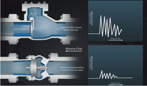
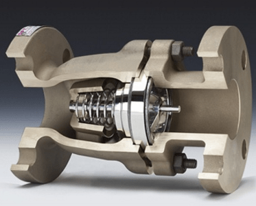
+ Non-return valve:
In section 3.5, warnings were given about the dangers of using the wrong types of nonreturn valves when significant water hammer is possible. However, sometimes a non-return valve is needed to prevent the formation of cavities due to reverse flow. The appropriate type of valve should be chosen according to the situation under consideration.
+ High inertia pump:
The potential danger from a low inertia pump was described. Hence a normal pump feeding a long pipeline is a surge risk. If the inertia is increased, this stores energy and so the pump and the liquid will slow down more gradually. The increase required might be small, such as a large or magnetic coupling. In other cases, a flywheel can be placed in the pump drive.
6. HOW TO ANALYSE A PIPING SYSTEM FOR RISK OF WATER HAMMER?
Having performed the simple calculations from the foregoing equations and found that there is a risk of water hammer, it is necessary to do some more detailed computation. Dynamic analysis of pipe systems is often a complicated, lengthy and expensive procedure, and so the steps shown in Figure 10 are recommended before embarking on full dynamic computer models.

Due to the specialized nature of computer modelling and the costs involved, it is sensible to attempt cheaper solutions first. Reference 8 presents a logical procedure to examine a system without computer simulation, and a spreadsheet has been developed helps distinguish between problematic and problem-free systems without dynamic modelling (Reference 1).
If this indicates a need for further analysis, then a detailed computer model needs to be considered. Again there are several options for the engineer.
SOFTWARE WITH COMPLEX MODELLING CAPABILITIES
There are several excellent programs that are capable of modelling very detailed and complex piping systems, including:
– Flowmaster (Flowmaster Ltd)
– Wanda (Delft University)
– Hammer (Haestad Systems)
– Pipenet (Sunrise Systems)
These are expensive programs and require skilled use. It is often possible for the casual user to make mistakes due to the versatility and variety of the models and facilities present in the package. However for complex situations such as branched networks, partially full pipes, emptying and filling of pipes, and complex rheology, these programs give the best solutions available. Fees are in the order of £10,000 per year for these packages.
The author is not fully familiar with all of these packages, but is aware that they use the same mathematical technique, and are capable of highly accurate modelling. Some vendors have used practical apparatus set up specifically to produce results that can be compared with the results coming from the software. There are also “standard” results available against which software developers can test their product.
SOFTWARE WITH LIMITED MODELLING CAPABILITIES
There are other packages cheaper than those mentioned above that are less comprehensive in their capabilities. However they still use the mathematical method that is recognized as best for solving this type of problem (the “method of characteristics”) and as such can be relied upon to do safe analyses of simpler problems. These include:
. HiTrans (Reference 3)
. Hytran ((Reference 7)
These programs tend to come from smaller organizations that do not have the resources to conduct their own practical tests. However the author has run problems on both Flowmaster and HiTrans and found similar results. Flowmaster can deal with more complex situations than HiTrans, but he found that every problem he has dealt with in chemical factories to date could be modelled on both programs. Fees for these are from a few hundred pounds for outright purchase.
These programs all describe the pipe system as a series of nodes with pipes in between them. The modeller is free to choose the nodes. Ideally the system would be described by as many nodes as there are bends in the pipe. However sometimes this is impractical and unnecessary, and shorter sections of pipe can be amalgamated in the model.
INTERPRETATION OF RESULTS
Models have to be carefully written to give the results needed. They must be written to
represent the system being studied so that all important events such as startup, shutdown, emergency shutdown, power failure etc., can be studied. Once the model has been written, scenarios representing these events are run. All runs then have to be analysed. The first steps are:
1. Look for high and low pressures in the system
2. Look for the formation of cavities (or pressure falling below the liquid vapour pressure).
These need to be compared with practical limitations, such as the maximum and minimum allowed pressure in the pipe, and the maximum force allowed on the pipe supports.
The pressure-time history produced by modelling software is usually complex due to reflection and interference of waves. At any point in the pipe, the change in pressure with time can be plotted, and examined to determine what the maximum and minimum pressures were, and to deduce the forces produced by them at that point. The whole pipe length has to be examined this way.
To calculate the force that might appear in a section of the pipe, it is necessary to look for the maximum pressure step that can “fit” in the pipe. The software operates by calculating the pressures and flowrates in the system at each node at many timesteps over the period of time that the modeller wants to study. It is possible to look at the sections of pipe and the pressure-time history of the nodes next to it, and look for times when the pressure has been changing rapidly. Instantaneous events take place over one timestep, and will fit into any length of pipe (Figure 8, first diagram). The coloured bar represents a certain pipe in units of time taken for the wave celeric to traverse it. It is a short pipe, and only a rapid pressure change can fit into it. Slower changes in pressure will not fit into short pipes as the leading edge of the pressure wave has turned the next corner before the trailing edge gets into the pipe. In this case, it is only the pressure change that can fit into a pipe that produces an out-of-balance force in the pipe. For a longer pipe (Figure 8, second diagram), not only an instantaneous event, but also part or all of a more gradual change, can result in a force in the pipe.
7. Summary:
– Water hammer occurs when the kinetic energy of a fluid is converted into elastic energy. But only rapid changes of the flow velocity will produce this effect, for example the sudden closure of a gate valve or the sudden failure or tripping of a pump. Due to the inertia of the fluid, the flow velocity of the liquid column as a whole is no longer capable of adjusting to the new situation.
– The fluid is deformed, with pressure transients accompanying the deformation process. The reason why surge pressure is so dangerous is that it travels at the almost undiminished speed of sound (roughly 1000 m/s for a large number of pipe materials) and causes destruction in every part of the piping system it reaches.
– To avoid water hummer can use surge tank and the total volume of the air vessel consists of the volume of fluid in the vessel and the gas volume. The usual minimum and maximum values used for initial gas volume are 25% and 75% of total tank volume.
– Water hammer can cause severe problems in the system if not designed properly. So at the time of designing of the system potential water hammer problems should be considered for thorough analysis. And proper methods or devices are to be used so as to assure the proper functioning of the system and to lessen the effect of water hammer.
– Water hammer is useful in certain cases as hydraulic ram, mine clearing etc.
Pls see previous part: Water hammer in piping system ( Part 1 )

3 thoughts on “Water hammer in piping system ( Part 2 )”