
")
Continuing on MARINE COROSSION AND PROTECTION (Part 1) that we discussed about the Electro-chemical corrosion protection methods and the last remained one is called ICCP system.
Reversing the current by creating an opposite potential ( ICCP : Impressed current corrosion protection )
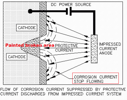
The ICCP system, a large positive current is applied to hull and pass through the adjacent water. As a result, current flow into ship’s steel whereas it has a direct unprotected contact with seawater and inducing a Cathodic reaction that protect the steel against the corrosion.

To achieve this, the Rectifier (convert AC–>DC) is connected to ship’s steel with Negative exit. The Positive exit is connect to two or more special Anodes are embedded in the hull to prevent damage by floating objects and made by inert material ( non-reactive ) like platinum – very expansive, thus the non-reactive anodes has no metal to consume, the reaction will create Oxygen bubbles which are not harm to the shell.

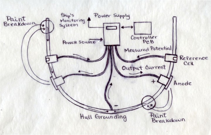
General, the strength of impressed current is 10A to 600A depended on the size of ship, the Voltage is 20V – 30V (painted condition) depended on the number and position of anodes ( but the voltage will reduce to 1.5 – 2V at the hull direct contact to seawater).
Notes for ICCP system:
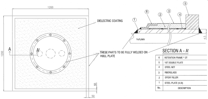
1-The most important area here is the dielectric shielding system . This is applied to the area of the hull immediately behind and adjacent to the active anode element. In most systems this consists of two areas, a primary and secondary shield (Fiber glass + epoxy). The integrity of this shield is critical if the ICCP system is to distribute protective current to all areas of the hull.
Any damage to the shield will result in unacceptably high potentials on the exposed hull (if the anode is operated anywhere close to its rated current). This normally results in hydrogen evolution (Many bubbles surround the anodes) at the steel hull surface, which causes progressive dis-bondment failure of the shield to the point where the anode can no longer be operated.

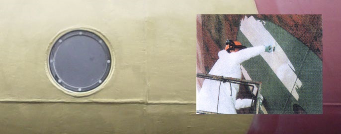
2- The paint layer may be damaged by overprotecting current due to the System failure and Dielectric shielding broken.
3-Earthing ground required for Rudder and Propeller shaft.
Even on ships fitted with ICCP or sacrificial anode systems, propeller shaft bearings are vulnerable to corrosion. This is because turning shafts are electrically insulated from the hull by the lubricating oil film in the bearings and by the use of non-metallic bearings (ex: Thordon bearing) in the tail shaft.
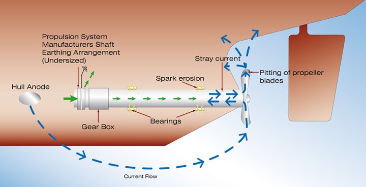
Whilst the shaft is turning the bearing lubrication creates an intermittent high resistance which effectively insulates the propeller from the hull structure and since the propeller presents a relatively large surface area of bare metal, it attracts cathodic protection currents, which tend to discharge by arcing across the lubrication film and in so doing, results in spark erosion which eventually leads to pitting and ‘striping’ of white metal bearing surfaces.
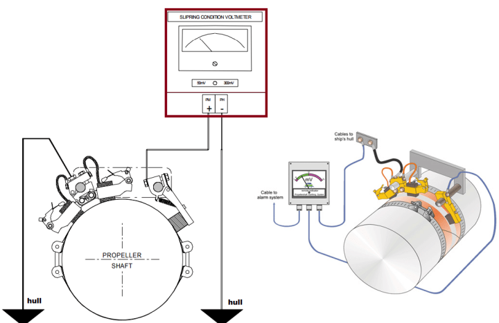
It is generally accepted, that the effects of arcing are minimised when the potential across the shaft/hull interface is less than 50 mV.

3 thoughts on “MARINE COROSSION AND PROTECTION (Part 2)”