

To prevent leakage of the loading fluid, an optical precision on the order of three light beads/bands [0.0000348 in. (0.0008838 mm)] must be maintained in the flatness of seating surfaces on metal-seated pressure relief valves (see API 527). Imperfections in these seating surfaces may contribute to improper valve action in service.
What is Light Bands
Light Bands were discovered by Isaac Newton who first studied them in 1717. They are an interference pattern created by the reflection of light between two surfaces.
When using a monochromatic light source it is possible to use the phenomenon to calculate the flatness of a component, but the surface of the component must be reflective in order for the light bands to appear. The light bands are made up of a bright and dark fringe. Combined, these correspond to the wavelength of the monochromatic light which in the case of a Sodium light source is equal to 589nm. When checking parts for flatness, it is only the dark bands that are counted, so as this is half the total fringe, each dark band equals 294nm or 0.00029mm.
Diamond lapping processes are ideal for producing reflective surfaces, which can be measured for flatness using this method directly after the lapping operation.
What is Lapping?

Lapping is a mechanical precision finishing operation done to achieve high dimensional accuracy.

It helps achieve positive sealing by obtaining a high degree of flatness and surface finish.

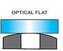
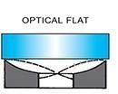
How to read light bands with an Optical Flat
First, clean the surfaces of the component and optical flat with lens tissue or soft lint-free cloth. Both faces must be absolutely clean. Place the optical flat carefully on top of the component. Do not slide it across. As the optical flat and component come together lines will appear through the flat. Manipulate it to obtain a line pattern, as illustrated. The lines are interference fringes or bands and are an indication of the level the component’s surface has risen or fallen in relation to the optical flat.
Flatness is measured using a Monochromatic lamp & Optical flat.
The Monochromatic lamp unit provides a light source with a sodium vapor lamp. The wavelength of Sodium light in the air (λ air): 0. 000589mm i.e. 0. 589 micrometers

Unit for flatness measurement is half the wavelength i.e. λ / 2 = 0.000589 / 2 = 0. 0002945mm (rounded off to 0.0003mm i.e. 0.3 micrometer)
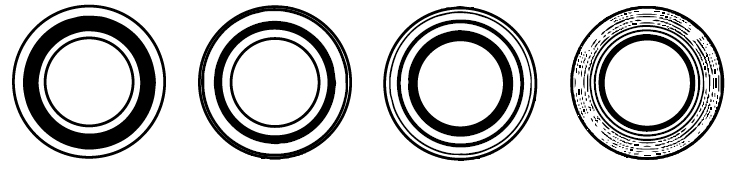
| Surface geometry | 1 Light band 0.00029mm |
2 Light bands 0.00058mm |
3 Light bands 0.00087mm |
9 Light bands 0.00261mm |
|
|---|---|---|---|---|---|
Convex or ConcaveSurface parallel to flat |
 |
 |
|||
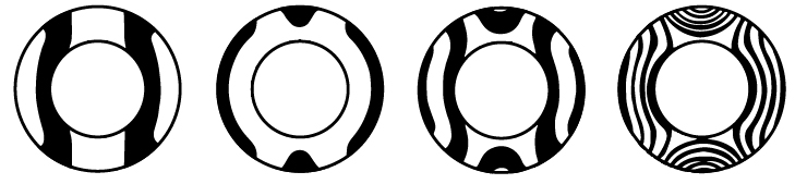
ConvexWith concave surface band will curve in opposite direction |
 |
 |
|||
CylindricalConvex or Concave |
 |
 |
|||
Saddle ShapedSymmetrical Pattern |
 |
 |
|||
