

This article will guide you about the general specification for steel line pipe and pipeline from the requirements for manufacturing, testing, inspecting, marking, and shipping of steel line pipe for gas and liquid pipelines for offshore applications at purchasing stage or vendor document review process.
The following documents are considered part of this specification. Use the edition of each referenced document in effect on the date of the publication of this specification.
| API SPEC 5L | Specification of Line Pipe |
| API RP 5L1 | Recommended Practice for Railroad Transportation of Line Pipe |
| API RP 5LW | Recommended Practice for Transportation of Line Pipe on Barges and Marine Vessels |
| ASTM A-370 | Methods and Definitions for Mechanical Testing of Steel Products |
| NACE TM-0284 | Evaluation of Pipeline and Pressure Vessel Steels for Resistance to Hydrogen-Induced Cracking |
| NACE MR-0175 | Sulfide Stress Cracking Resistant Metallic Materials for Oilfield Equipment |
Highlighted Manufacturing Process Requirements
- The Supplier should provide a controlled copy of the Manufacturing Procedure Specification (MPS) and Manufacturing Quality Plan (MQP) that is customized to meet the requirements of the purchase order and this Specification.
- All pipes should be manufactured in accordance with API Specification 5L.
- Only seamless (SMLS), submerged arc welded (SAW), or electric welded (EW) pipe should be used.
- Pipe should be made from a fully-killed (See what is Rimmed Steel, Semi-killed Steel, Fully killed steel), continuous cast or pressure cast steel.
- Ends of pipe should be machined as specified in API Specification 5L, with a bevel angle of 30 degrees, plus 5 degrees, minus 0 degree. Maximum deviation of the plane of the pipe end from a plane perpendicular to the longitudinal axis through the center should be 1/32” for pipe 10-3/4” OD and smaller, and 1/16” for pipe 12-3/4” OD and larger.
- Mill-welded jointers are not acceptable unless agreed to in writing by Buyer.
- Pipe may be either non-expanded or cold expanded. Cold expansion should not exceed 1.5 percent strain (benefit in case of pipe out of roundness tolerance and need to be cold-work).
- Pipe lengths should be minimum 39’6” and maximum 40’6”, with the average length as near to 40’ as possible.
- The use of diameter tapes to measure the minimum outside diameter for pipe with a 20” OD and smaller as stated in API Specification 5L, Table 6.3, “Pipe Ends” section, is not acceptable.
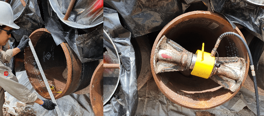
- The maximum ovality should be 1.5% for pipe sizes up to NPS 24 inches, and 1% for sizes greater than NPS 24 inches.
- The ID tolerance should be +/- 0.06 inches (1.5 mm), unless waived in writing (Some project spec. can allow to 2-3mm if the welding alignment-fit-up has no issue).
- The Supplier should include the following items with his quotation:
- A brief description of all steel and pipe making operations and practices, particularly ladle treatments for desulfurization, inclusion shape control if practiced, casting, skelp, or plate rolling practices, and monitoring procedures for weld heat treatments if applicable.
- A brief description of pipe mill operations, including all destructive and nondestructive testing equipment, a flow diagram including the location of this equipment in the mill, and flux moisture control systems for submerged-arc welded pipe.
- The final heat treatment condition of the pipe (as rolled, normalized, quenched and tempered, etc.).
Highlighted Chemical Properties and Tests Requirement
- Unless otherwise specified, the carbon content %C should not be less than 0.05%
- The steel should have a Carbon Equivalent (C.E.) not greater than 0.42
- Silicon content should not exceed 0.35%, sulfur content should not exceed 0.015%, and phosphorus content should not exceed 0.025%
- When added, the Columbium (Co) plus Vanadium (V) plus Titanium (Ti) content should not exceed 0.12% total. Any other intentionally added elements such as nitrogen, aluminum, calcium, or other deoxidizers or grain refiners should be reported.
- Supplier should include with his quotation the nominal chemical compositions (not API Specification 5L Table 3.1 maximums) of all elements in the steel that the Supplier proposes to supply. Typical ranges for all significant elements in the steel should be reported.
The product chemical composition should meet the following requirements:
| ELEMENT | SAW-PIPE | EW or ERW-PIPE |
|---|---|---|
| Carbon (C) | 0.05-0.10% | 0.05-0.10% |
| Manganese (Mn) | Per API 5L 3.1 * | Per API 5L 3.1 * |
| Silicon (Si) | 0.35% max. | 0.35% max. |
| Sulfur (S) | 0.003% max. | 0.003% max. |
| Phosphorus (P) | 0.012% max. | 0.012% max. |
| Nickel (Ni) | 0.20% max. | 0.20% max. |
| Chromium (Cr) | 0.20% max. | 0.20% max. |
| Molybdenum (Mo) | 0.20% max. | 0.20% max. |
| Copper (Cu) | 0.35% max. | 0.35% max. |
| Aluminum (Al) | 0.05% max. | 0.05% max. |
| Calcium (Ca) | 2X Sulfur min. / 0.006% max. | 2X Sulfur min. / 0.006% max. |
| Nitrogen (N) | 0.012 max. | 0.012 max. |
| Niobium (Nb) | 0.08% max. | 0.08% max. |
| Titanium (Ti) | 0.025% max. | 0.025% max. |
| Vanadium (V) | 0.08% max. | 0.08% max. |
| Nb + Ti + V | 0.12% max. | 0.12% max. |
| Carbon Equivalent (IIW) | 0.38% max. | 0.38% max. |
* The maximum allowable Manganese content is that listed in Table 3.1 of API 5L Table 2B. Manganese content increases based on carbon content are not permitted.
If the purchase order Data Sheet states that the pipe will be induction bent, the Supplier should ensure the appropriate base metal and welding consumable compositions are chosen to achieve the specified mechanical properties after bending.
Highlighted Mechanical Properties and Tests
- Tensile strength (UTS) should not exceed specified minimums by more than 20,000 psi. The maximum yield/tensile strength ratio should be 0.90 unless otherwise specified.
- For pipe sizes NPS 8 and larger, longitudinal base metal tensile tests should be required in addition to the transverse base metal tensile tests required by API Specification 5L. The same properties should be guaranteed in both longitudinal and transverse directions, according to API Specification 5L and this Specification.
- The Charpy V-notch specimens should be tested according to API 5L Supplementary Requirement SR5B. The Charpy Impact toughness requirements in foot-lbs should be as stated in the following table.
| Pipe Grade | Avg. V-notch Charpy ft-lbs (full size) | Min. V-Notch Charpy ft-lbs (full size) | Minimum Shear Requirements, all specimens, percent |
|---|---|---|---|
| Grade B thru X-56 | 30 | 22 | APL 5L SR 5A |
| X-60 | 32 | 24 | APL 5L SR 5A |
| X-65 | 35 | 27 | APL 5L SR 5A |
| X-70 | 40 | 30 | APL 5L SR 5A |
- The test temperature should be 32°F or the minimum service temperature of the line, whichever is lower.
- A stress-strain curve should be produced on one pipe from each of the first five heats of pipe for information purposes. This information should be submitted as part of the data package in SR 15.1c.
- If pipe is to be reeled, one pipe from each of the three heats should also include a tensile test at ambient temperature and impact test at 32°F on material given a 3% longitudinal tensile stain followed by aging at 250°C for one hour. The results of these tests conducted in longitudinal direction should conform to the Charpy requirements of this Specification. Retests should be permitted per API 5L.
Hydrostatic Testing
- Hydrostatic tests should be done in accordance with API Specification 5L except that the pipe should be tested at a pressure that produces a hoop stress of 95% or more of the specified minimum yield strength (SMYS), based on nominal wall thickness. Appendix K for end load compensation may be used, but in no case should the test pressure produce a stress of less than 90% SMYS. Test pressures should be maintained for a minimum of ten (10) seconds.
- End seals used for hydrostatic test should not obstruct the test or the observation of the pipe for more than 2 inches on each end of each joint. If Supplier is unable to comply with this, the distance of obstruction should be stated in his quotation.
Material Testing and Reporting
Two copies of each of the following test or analyses records, conducted in accordance with and conforming to the requirements in API Specification 5L and this Specification, are required and should be furnished to Buyer. Records and reports should include the following:
- Order number, pipe outside diameter, wall thickness, weight per foot, type of weld seam (if any), and grade.
- Heat and check analyses of each heat and lot on the finished pipe. The total steel composition, including silicon, micro-alloying elements added for improved hardenability, and carbon equivalent should be reported.
- Tensile properties (ultimate tensile strength, yield strength, and percent elongation) for each lot and mill control tensile tests for each heat.
- Impact test results.
- If the pipe is cold expanded, the maximum amount of expansion should be reported.
- Hydrostatic test results.
- Non-destructive inspection records and logs.
Nondestructive Inspection
- Seamless pipe should be nondestructively inspected after hydrotesting in accordance with API Specification 5L Supplementary Requirement, SR-4, except as follows:
- The only acceptable electromagnetic method is that which utilizes diverted flux.
- Ultrasonic testing is required for wall thickness greater than 0.4 inches.
- Electromagnetic inspection may be permitted for wall thickness to 0.5 inches if the Supplier can demonstrate the equipment effectiveness, including inspection procedures.
- The reference standard in API 6.1.3 should be used to demonstrate said effectiveness.
- A dynamic calibration at production speed using the reference standard is required. As a minimum, calibrations should be done at the start of each shift and before the nondestructive unit is turned off. If the latter calibration check shows that the accuracy of the calibration has shifted outside of the acceptable range, all lengths of pipe inspected since the last good calibration should be re-inspected using the same nondestructive method previously used.
- If necessary to meet the full length (100%) inspection requirements of SR-4.1, pipe ends should be inspected by using hand-held ultrasonic shear wave equipment or the end length not receiving an inspection should be cut off.
- The Supplier should provide their inspection procedures for Buyer approval prior to pipe manufacture.
Workmanship, Visual Examination, and Repair of Defects
- Surface defects should be acceptable without dressing only if their extent may be readily assessed by visual examination by Buyer. Burrs and sharp projections should be removed from the outside surface of the pipe by grinding. Where burns, seams, scabs, roll marks, sharp scratches, other damages or flaws, etc., of unknown depth are found, suitable nondestructive examination methods or surface grinding should be performed to assure that the depth of the imperfection is less than 12.5% of the specified wall thickness. When the surface is ground to remove a surface imperfection, complete removal should be verified by magnetic particle examination and the remaining wall thickness measured by UT to assure it meets or exceeds minimum API allowable requirements.
- Repairs to defective seamless pipe are not permitted.
- When defects or deviations which approach but are within defined limits of this Specification and of API Specification 5L occur repeatedly on successive pieces, they may cumulatively constitute an “injurious defect” and therefore be cause for rejection on the basis of workmanship. The cause for such repeated defects should be corrected when called to attention of the Supplier in writing by Buyer. Thereafter, Buyer will not accept responsibility to accept subsequent production containing such repetitive defects or deviations.
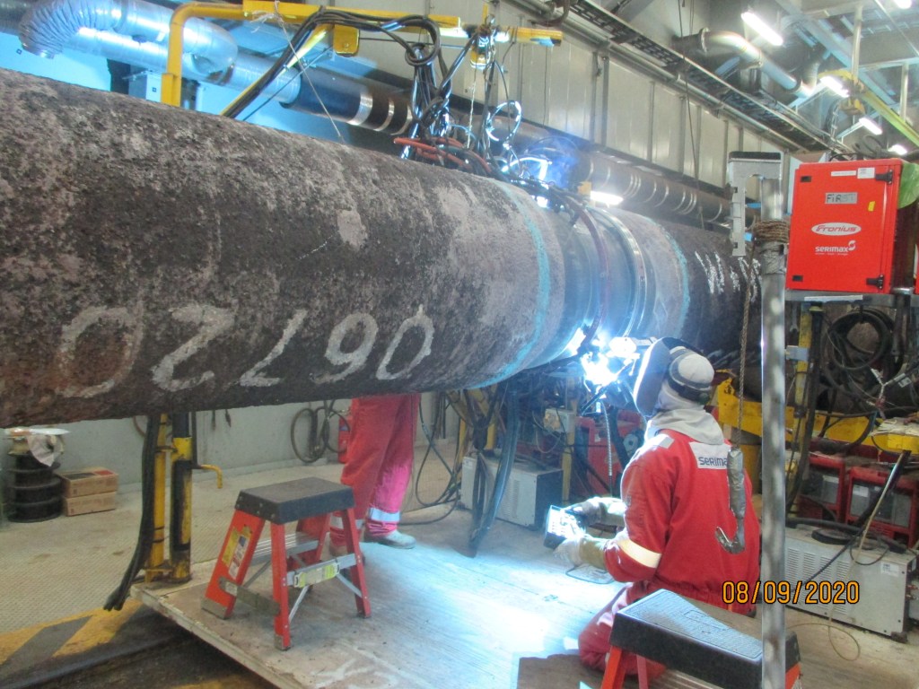
Repairs to welded pipe should be in strict accordance with API Specification 5L with the following additional requirements:
- Repair welding is not permitted outside the weld zone.
- Multiple repairs of the same location are not permitted.
- Repaired areas should be nondestructively inspected by radiography onto suitable film or by manual ultrasonic inspection.
- Repair welding procedures should be qualified according to Appendix B of API Specification 5L.
- Repair welding procedure qualifications should include hardness traverses on a metallographic cross section of the weld at 2-3 mm below the cap pass and at 1-2 mm above the root. Each traverse should include readings at a maximum of 1 mm intervals in the base metal, HAZ, and weld metal (at least three readings in each zone) on both sides of the weld. No values should exceed 250 HV10. The composition of the deposited weld metal should not exceed 1% Ni for all repair welds.
Pipe Marking
- Each length of pipe should be marked as specified in API Specification 5L. Pipe should be traceable by pipe number back to heat treatment.
- In addition, the measured length, specified diameter, wall thickness, and joint number should be paint stenciled or paint-stick marked on both ends of each joint. For pipe sizes larger than 10 inches O.D., this marking should be on the inside surface; for smaller sizes it may be on the outside and an identifying daub or paint should be placed on the inside. Buyer reserves the right to specify the colors to be used for identification.
- Cold die stamping of the finished pipe is prohibited unless it is required by regulatory bodies. In that case, low stress rounded dot stamps should be used and all stamping should be done on the weld bevel.
Pipe Mill Certification (MTC)
All analyses are to be certified and the Buyer should witness all mechanical tests when possible, in accordance with API Specification 5L, Appendix G.
Quality Assurance Provisions
The line pipe purchased should be covered by the following supplementary warranty clause:
- Buyer will be reimbursed for replacement costs of any pipe furnished that fails under field hydrostatic test due to defects of material, workmanship, or lack of compliance with this Specification. Such tests should be applied at the time of construction and before line pipe is placed in service. These replacement costs should include pipe, labor, and equipment rental for locating, cutting out, and replacing defective pipe.
Buyer’s construction Specifications will require Supplier to adhere to the following test procedure for the field hydrostatic test, using water as the testing liquid, on any pipeline purchased under above warranty.
- The test pressure should be 150 percent or more of the MAOP of the lowest rated element in the section under test. The pipeline should be designed such that the stress in the pipeline during the test does not exceed 90 percent SMYS of the pipeline.
- The pressure should be raised to a point 2 percent above the specified test pressure and held for one hour.
- Sufficient water should be released to lower the pressure to the specified test pressure. This pressure should be held for a minimum of four hours.
- The pressure should be released.
Preparation for Shipping
Pipe should be bare, dry and free of oil, grease, lacquer, antifreeze (from UST couplant) and other contaminants such as chlorides that adversely affect coating adhesion.
Pipe should be provided with bevel end protectors.
Line pipe transport should be in accordance with the Technical Requirements and API RP 5L1, “Recommended Practice for Railroad Transportation of Line Pipe” or API RP 5LW “Recommended Practice for Marine Transportation of Line Pipe on Barges and Marine Vessels” as applicable.
A loading diagram showing the stacking arrangements, location of bearing strips, use of spacers, tie-down straps, etc., should be furnished to the Buyer Representative for review prior to shipment.
Handling of pipe in the shipping yard should be with nylon slings or special type of end hooks with soft metal inserts subject to Buyer approval. No handling devices with copper or copper alloys may be used.
Trailer shipments may be made on pole trailers containing properly constructed hardwood cradles on the bolsters or on trailer floats. Pipe should be securely tied to trailer by use of banding material or padded chairs.
If in-transit fatigue cracks are detected after shipment, Buyer reserves the right to reject the entire shipment until an absence of fatigue cracking is proven on the entire shipment by an agreed-upon nondestructive examination method.

One thought on “Certification of Line-pipe for oil and gas service”