

This article outlines the minimum requirements for manufacturing of induction pipe bending according to ASME B31.8, ASME 16.49 and ISO 15590-1.
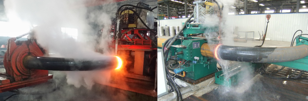
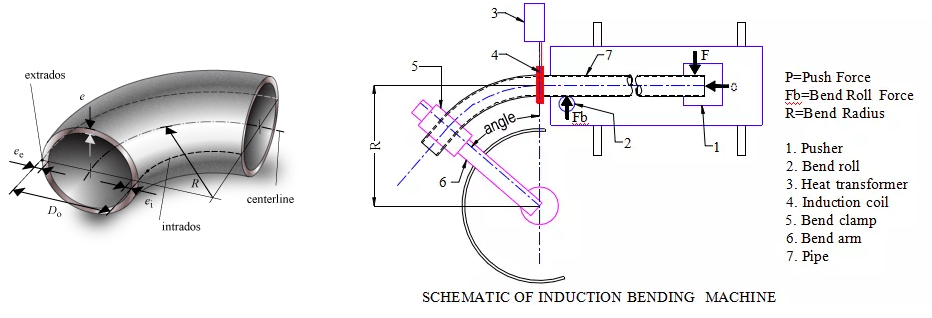
Induction Bending is formed by passing pipe through an induction bending machine. This machine uses an induction coil to heat a narrow band of the pipe material. As the pipe is pushed through the machine, a bend with the desired radius of curvature is produced. The heated material just beyond the induction coil is quenched with a water spray on the outside surface of the pipe. Thermal expansion of the narrowly heated section of pipe is restrained due to the unheated pipe on either side, which causes diameter shrinkage upon cooling.
The induction bending process also causes wall thinning on the extrados and thickening on the intrados. The severity of thinning/thickening is dependent upon the bending temperature, the speed at which the pipe is pushed through the induction coil, the placement of the induction coil relative to the pipe (closer to the intrados or extrados), and many other factors.
The following general guidelines should apply to the induction heating of pipe:
- If the pipe wall thickness varies around the circumference, the thicker section should form the bend extrados.
- No stoppage should be permitted once the bending operation has started.
- The maximum temperatures at two positions (180 degrees apart), the bending speed and the flow volume or pressure of cooling medium should be continuously indicated and recorded.
- The accuracy for temperature measurement should be + 10 oF (+ 5.5 oC); for speed should be + 0.02 in. (+ 0.5 mm) per minute, and for flow should be + 2% of flow specified in the Manufacturer’s Bending Procedure.
- If any of the Essential Variables, as listed in ASME 16.49 / ISO 15590-1 vary from those given in the qualified Manufacturer’s Bending Procedure by more than the tolerance given in ASME 16.49 / ISO 15590-1, the pipe should be discarded.
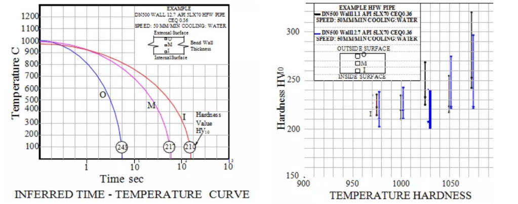
- It is a good practice to have maximum speed of bending between 25 – 50 mm/min, unless otherwise justified by the manufacturer. Also, cooling process should take place immediately behind the induction, this results in a short time Austenitizing cycle and a quenched metallurgical structure.
- Post Bend Heat Treatment – Bends should be heat treated after bending to fulfill the required high-quality level.
Prior to the start of induction bending, the manufacturer should qualify the Manufacturer’s Bending Procedure for Induction Bending by making and testing a Qualification Bend in accordance with ASME 16.49 / ISO 15590-1. The procedure qualification demonstrates that bends having acceptable dimensions and mechanical properties can be produced with the Manufacturer’s Bending Procedure.
- The Qualification Bend should be made using the same heat of material as the production bends and the proposed Manufacturer’s Bending Procedure.
- Post Bend Heat Treatment should be performed as part of the procedure qualification tests, and a detailed procedure should be included.
Manufacturer’s Bending Procedure should include, as a minimum, the following:
- Description of bending/heating equipment
- Induction bending temperature
- Expected temperature profile across the wall thickness
- Cooling procedure
- NDE procedure (Magnetic Particle, UT, etc.)
- Dimensional control equipment and procedure
The essential variables with their permissible variations permit to determine when it is necessary to re-qualified. Essential variables are about:
- Dimensions (diameter and wall thickness of mother pipe, bend radius)
- Forming (speed, temperature)
- Coolant (flow rate, pressure, temperature)
- Induction heating frequency
- Post Bending Heat Treatment
The maximum permissible variations should be as given in ISO 15590-1 Table 1.
Dimensions and Ovality
The following measurements and specifications should apply during the bending process:
- The wall thickness of the pipe for each bend should be measured ultrasonically before bending at approximately 300 mm intervals along both the inner and outer radii of the bend (between and including the start and stop points of the bend arc angle).
- The wall thickness of the pipe for each finished bend should be measured ultrasonically after bending at the same locations measured before bending. In addition, the wall thickness of the tangents should be measured mechanically. These measurements should be taken at four equally spaced locations around the pipe circumference at both welding ends of the bend.
- Ovality, as measured by the difference between maximum and minimum diameters and calculated per ASME 16.49 / ISO 15590-1 should not exceed 3% of the nominal diameter throughout the body of the bend and 1% for the tangent portions.

- The diameter should be measured at the start or stop of the bend locations and at all points throughout the bent portion to ensure compliance with the required tolerances.
- For subsea flexible riser: The internal diameter at any location of the bend should not be less than 95.7% of the nominal internal diameter of the pipe; and not less than 98.6% of the nominal internal diameter of the flexible riser.
- All other post-bend dimensions should be within the tolerances of ASME B16.49, Section 12 and ISO 15590-1.
Testing of Induction Bends
The minimum wall thickness at the midpoint of the extrados of for each production bend should be measured and recorded to confirm the wall thickness is equal to or greater than the required minimum wall thickness specified in the bend specification.
The entire pipe circumference 100 mm back from the beveled ends of each tangent length should be subjected to Ultrasonic Testing (UT) to confirm no lamination type defects are present. Areas that cause greater than 50 percent of back wall echo or cause a reflection equal to or greater than 50 percent should be cause of rejection of the bend.
Magnetic Particle (MP) examination should be applied to 100% of external surfaces that have been subjected to strain and the machined surfaces of the beveled ends. MP inspection should be in accordance with API 5L Section E.6 unless otherwise agreed.
Mechanical testing of induction bends should be completed as per the requirements of ISO 15590-1, ASME B16.49, Sections 11 and SR15.
Wall Thinning: The minimum wall thickness in the extrados of the test bend should not be less than the minimum required to meet the requirements of ASME B31.8 for the design pressure and the as-tested mechanical properties of the post bend material.
Inspection of Induction Bends
Each bend should be visually inspected on the inside and outside surface for cracks, laminations, gouges, or notches. Any crack, or any imperfection which might conceal a crack, should be removed in its entirety by grinding. There should be no weld repairs.
The dimensions of all induction bends, including wall thickness and ovality should be inspected as shown in above section and documented. Each bend should conform with the tolerances specified in ASME 16.49 Section 12 and ISO 15590-1.
The hardness of the steel pipe for all finished production bends should be determined at the point of maximum bending, 300 mm from the start and stop points of bending, and in both tangents:
- A minimum of two (2) measurements should be made at all locations at the extrados, intrados, and on each side at the neutral axis of the bend. To demonstrate uniformity between the qualification and production bends, each production bend should be hardness tested in all the same locations as the qualification bend; also consider hardness testing requirements from ASME 16.49 Section 11.2 and ISO 15590-1.
- Acceptable levels of accuracy and precision for all measurements should be demonstrated and documented.
In addition to the requirements of ASME 16.49 and ISO 15590-1, the following inspection should be conducted:
- At the beginning of bend and end of bend on the extrados, and at the mid-point of the intrados:
- 1 each transverse test with 6 each hardness tests on 2 mm grid spacing
- 3 each Charpy impact test on transverse specimens
- 1 each longitudinal tensile test with 6 each hardness tests on 2 mm grid spacing
- At the mid-point of the extrados, the same tests as listed for ends and intrados mid-point with the addition of a transverse tensile test in as bent condition prior to post bend heat treatment.
- The above mechanical tests are to confirm that the as-bent pipe meets or exceeds the mechanical properties of the pipe before bending.
Repair of Defects
Defects, including laps, shells and slivers may be removed by grinding to a smooth profile provided that the minimum allowable wall thickness is not encroached upon. Any repair grinding should leave a smooth surface profile and should be subject to full surface inspection by Magnetic Particle examination to confirm the defect has been removed and that the repair is acceptable.
Defective areas that extend more than 0.25 inch (6.35 mm) in the circumferential direction or any defects within 2.5 inch (63.5 mm) of the end bevels should not be repaired. If possible, such defects should be removed by cropping or re-beveling. If this is not possible, without cutting into the strained area, the bend should be discarded.
No correction of minor dimensional deviations using a heat source should be allowed after heat treatment.

No weld repairs to the body of the pipe should be allowed. Repair by welding of bends is not allowed.


One thought on “What is Hot Induction Bends and Inspection guides.”