

Two types “Shop test and After installation test”
First, the hydro-static test of spool at Workshop is prefer to check the quality or strength of Welding joints, integral fittings and confirm whether it can satisfy the rule/standards requirement.
TEST PRESSURE (Tp)= 1.5 DESIGN PRESSURE (Dp)
“But we can not do final all spools at workshop and just bring on-board for assembly because there’re many Field Joints waiting you ahead. Depend on the flexibility of Rule/Spec, the low pressure pipe’s field joints can be tested under max.working pressure”
Second, in ideal condition, no more welding joints on-board, the Leak test will be carried out after assembly on each individual system (can be combined if the test pressure is coincident) to confirm there no any leakage.
Tp = Dp, excepted for Hydraulic system, Fuel oil, Steam, Fire line … that Tp = 1.5 Dp (not need more than 70 bar – DNV). <Please care fully read the Rule and Spec>.
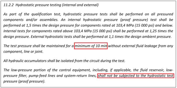
Refer to the ISO 13628-6
Concerning item:
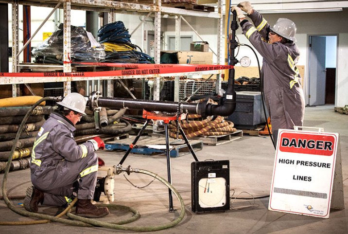
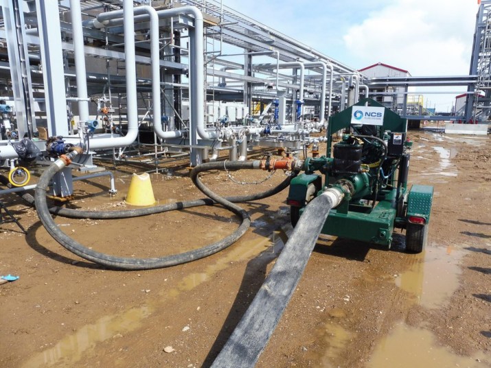
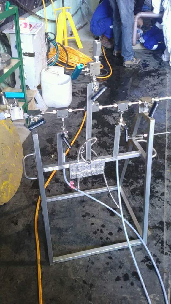
Test kits (gauges, manifold, blind flanges, vents, relief valve, water supplying hoses, water quality ect.,)
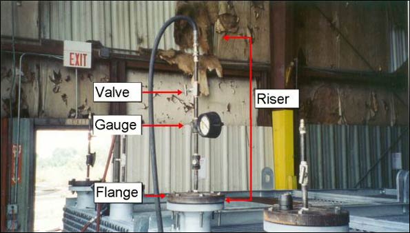
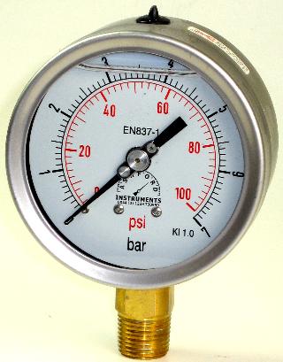
Note as advice: “the Pressure gauge range should to be in range of 1.5Tp to 4Tp and the Needle should not turn over 2/3 gauge range or Tp<2/3 Max.Gauge’s range”
Test kits secured due to high pressure
Pressure test calculation/ temp rating
In offshore project where the strictly compliance with code and standard is really a problems with all the fabricators.

Max.working pressure vs Design pressure.
Sometime, there’s confusion between those above concepts that leading to mis-understanding in final evaluation.
“The design pressure is defined as the maximum working pressure, and shall not be less than the highest set pressure of the safety valve or relief device. For special cases, the design pressure will be specially considered. For pipes which are connected to pumps, design pressure shall be taken equal to the maximum pump pressure, i.e. the safety valve set pressure for displacement pumps, and for centrifugal pumps the maximum pressure on the head-capacity characteristic.” – DNV Pt.4 Ch6 (A303)
Tip: The process engineer defines the design pressure by applying common and reasonable margins above the maximum operating pressure, as shown below.
|
Max. operating pressure |
Design pressure |
|---|---|
|
Atmospheric pressure |
0.5 barg |
|
Vacuum |
Full vacuum and 3.5 barg min. |
|
Between 0 and 10 barg |
Max. op. press. + 1 bar (3.5 barg min.) |
|
Between 10 barg and 35 barg |
Max. op. press. + 10 % min. |
|
Between 35 barg and 70 barg |
Max. op. press. + 3.5 bar min. |
|
Above 70 barg |
Max. op. press. + 5 % min. |
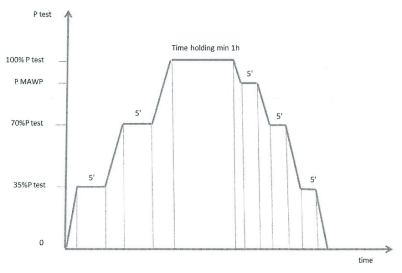
Holding time and release procedure
In shipbuilding industry, the piping system carried out with low pressure and less toxic contented liquid, thereby at the time of inspection – no leakage – satisfying enough!!!
Meanwhile, in offshore building, the piping system like process piping will be suffer to very high pressure (up to 600-800 bars) and carried out with high toxic contented gas/liquid. So the pressure raising sequence and dropping sequence is specially concerned in testing procedure for making equalization of piping strain/ stress.

Problems with Pressure Drop/Increase due to Cold/Hot condition
In case of pressure increase, there may a potential of material damages or cracking propaganda. Piping team should be aware and control the temperature properly ( Ice can be use for cooling down sometime ) for nice plot Chart record.
The problems with pressure drop is always be serious concerned, 2%-5% allowable for the Drop depended on Project specification.

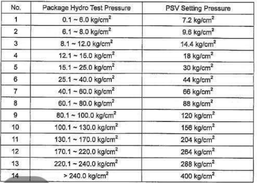
Safety requirement
The PSV setting 1.1-1.2 Tp is general practice.
Coating and insulation condition
All the weld joints have to be cleaned (no insulation, no paint), Primer may be used as per the contract agreement.

3 thoughts on “PIPING HYDRO-STATIC TEST COMPREHENSION”