As a common hydrostatic test procedure, the test pressure will be taken from the piping system MAWP. Depending on the primary code applied, the test pressure can be 1.5 MAWP, or 1.3 MAWP + factors, or 1.15 MAWP… etc.,
Refer to What is MAWP, What is Max operation pressure, Hydrostatic test:
What is the MAWP of the pressure vessel (ASME VIII)
FITTING PRESSURE RATING
PIPE PRESSURE RATING
PIPING HYDRO-STATIC TEST COMPREHENSION
Test Pressure vs MAWP (ASME VIII)
Design Pressure Vs MAWP (API, ASME)
MAWP is normally referred to as system maximum allowance working pressure. The fitting is small and is sometimes missing from the initial design at the beginning.
Thereby, after referring to all the above topics about the hydrostatic tests for piping, pressure vessels, we will try to go a little bit further on Fitting Pressure Rating that may affect the Test pressure.
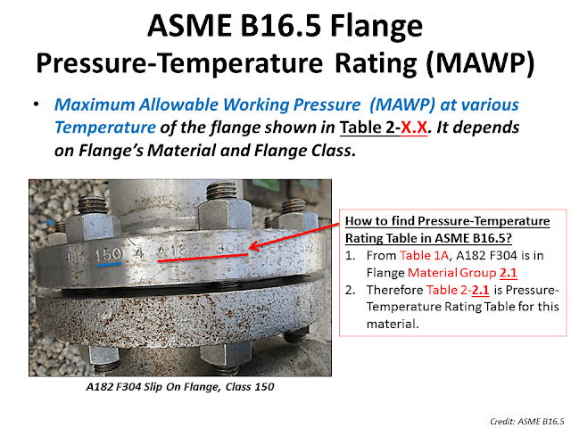
ASME B16.5 Flange MAWP, Pressure-Temperature Rating:
Flange designed according to ASME B16.5 is specified to have the Maximum Allowable Working Pressure (MAWP) according to the material strength (Yield strength), Flange Class, and the operating temperature.
In Code ASME B16.5, flange material is divided into groups (Flange Material Group) based on strength. It can be seen from Table 1A by Material Spec / Group.
Pressure-Temperature Rating Chart, Table 2.XX (XX = Material Group Number), which tells the MAWP of the Flange by the Flange Class and the operating temperature.
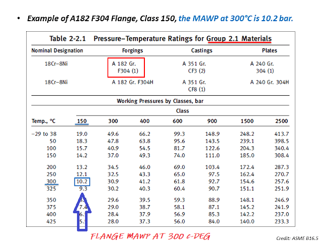
(For example) Flange – A182, F304, Class 150, operating at 300 C-deg:
1. Find the Flange Material Group from Table A1, A182 F304 in Material Group 2.1.
2. Go to Pressure-Temperature Rating Chart, Table 2.2.1, MAWP at 300 C-Deg for Flange Class 150 equals 10.2 bar and 19.0 bar for ambient (38 C-Deg) temperature (Shop hydrostatic test condition)
Now, we go to checking the System Hydrostatic Testing on Flanges (others are fittings, valves, or instruments) :
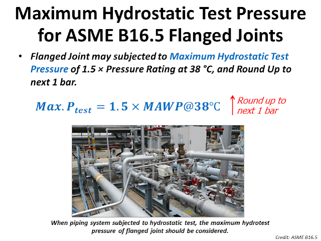
Maximum Hydrostatic Test Pressure for ASME B16.5 Flanged Joints:
The Code ASME B16.5 set the Maximum Hydrotest on Pressure of Flange Joint must not exceed 1.5 times the MAWP of Flange at 38 C-Deg
–> Calculate 1.5 times of MAWP at 38 C-Deg = 1.5 x 19 = 30 bar
Finally, check with the system hydrostatic test pressure (it’s normally mentioned in P&ID drawing). If the Test pressure is over 30 Bar –> DESIGN PROBLEMS

")

One thought on “Hydrostatic test with Flange Joints (considering of Flange MAWP)”