

OIL FLUSHING
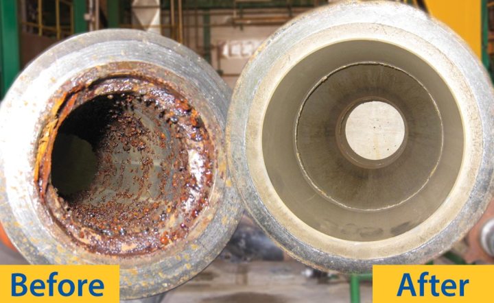
The purpose of oil flushing is to make sure the pipelines and operation oil is clean and free from contamination. Normally oil flushing is carrying out after the chemical flushing and for some pipelines only oil flushing is carries out.
In general, oil flushing is a cleaning method applied to lube oil/ hydraulic systems.

The concept of flushing involves loosening and removing contamination particles inside the system by forcing flushing fluid through it at high velocity.
Typical flushing procedure state that flushing must be accomplished at normal system fluid velocities for a certain period of time with a certain level of filtration. More stringent specifications may call for a particular fluid contamination level and require documentation by fluid contamination analysis.
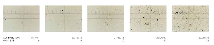
Oil flushing must be continuing until the target cleanliness code is achieved. Normally target cleanliness code one step lower than require level – Smaller mean Better.
Example, if require ISO4406:1999 class 18/17/16, the target cleanliness code should be 17/16/15. If require cleanliness code on NAS standard, the same target will be use. Example, if require code is class 9, the target code should be class 8.
How high a velocity?
The critical variable in flushing to achieve acceptable fluid and conductor cleanliness is fluid velocity. Traditional flushing methods usually establish this velocity in one of two ways:
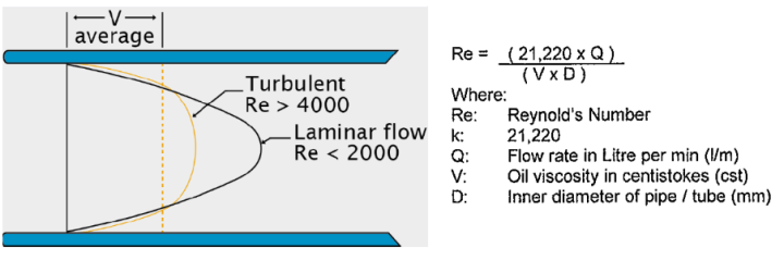
• the velocity must be high enough to achieve a Reynolds Number (NR) of 4000 for Piping and of 3000 for Tubing 1/2″ and below, or
• the velocity must meet or exceed the system fluid’s normal operating velocity as designed.
Nevertheless, experience has shown that neither of these flushing velocities is sufficient to assure the cleanliness of the system’s piping.
Because the viscosity of a typical hydraulic fluid is influenced by temperature and pressure. That is, the hotter the oil, the higher the Reynolds number for the same fluid velocity and pressure. The higher the pressure, the lower the Reynolds number for the same fluid velocity and temperature. Thus, specifying that Reynolds number should be 4,000/3000 is “not a stringent enough” requirement.
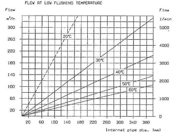
The temperature of the fluid directly affects its viscosity and is the other variable that can control Reynolds number. Flushing pressure also affects viscosity, but this is hard to quantify because pressure in the pipe being flushed will vary from maximum at the pumping source to atmospheric at the piping outlet, hence the pressure affections should be exempted during flushing evaluation.
To achieve the cleanliness during flushing below steps should be taking as guidelines:
- Turbulent flow must be given during flushing in order to remove dirt, debris and any foreign contamination. Calculation can be made to calculate the require flow to achieve turbulent depending on pipe size and oil viscosity.
- Low viscosity flushing oil should be select which can easily contribute for turbulent flow.
- Special inhibitor added flushing oil should be select in order to reduce corrosion attack on recent chemical flush pipelines.
- Temperature should be control through the process in order to achieve the quality oil flushing job.
- Only fiberglass filter media with minimum of 75 beta should be select as filter element for oil flushing. Micron size can be select according to target cleanliness class.

| TYPE OF HYDRAULIC SYSTEM | MINIMUM RECOMMENDED CLEANLINESS LEVEL | MINIMUM RECOMMENDED FILTRATION LEVEL IN MICRONS (Bχ ≥75) | ||
| ISO 4406 | NAS 1638 | SAE 749 | ||
| Silt Sensitive | 13/10 | 4 | 1 | 2 |
| Servo | 14/11 | 5 | 2 | 3 to 5 |
| High Pressure
(250 to 400 bar) |
15/12 | 6 | 3 | 5 to 10 |
| Normal Pressure
(150 to 250 bar) |
16/13 | 7 | 4 | 10 to 12 |
| Medium Pressure
(50 to 150 bar) |
18/15 | 9 | 6 | 12 to 15 |
| Low Pressure
(< 50 bar) |
19/16 | 10 | – | 15 to 25 |
| Large Clearance | 21/18 | 12 | – | 25 to 40 |
-
- At the beginning, we can use the rough filter 60mesh (238 micron) /100mesh (149 micron) /200 mesh (74 micron) for pre-cleanning then reduce the micron size as per above recommendation table.
- At least one filter on delivery line and second filter on return line must be installed. Monitoring of oil cleanliness sample must be taken on-line before the second return filter.
- Pulsation flow should be given for large pipelines as well small pipelines to increase oil flushing pushing power.
- Contamination level must be monitor on-line through the oil flushing process.
- Water content should be monitor through the oil flushing process and if require water adsorbent filter or water remover purifier can be mounted and operating off line.

- Looping hoses or connector must be hanging and clean before looping joint.
- Looping for the pipelines must be same as pipelines internal diameter.
- Magnetic filter can be installed on return line filter to catch ferrous practical and on the same time reduce number of filter element used.


3 thoughts on “Pipe Flushing (Full procedure, standards NAS, Filter selection, magnetic filter config.)”