


General
Defects in construction usually cannot be detected after the fabrication and welding work has been finished. During in shop fabrication the precise accuracy of this process will govern the final accuracy of the assembly unit. The surveyor should engage in frequent patrol inspections, taking every possible opportunity available on the way to or from the block yard to carry out block inspections or from building berth for tightness tests etc. He has to pass the fabrication shops to see the prefabrication process such as surface treatment, marking, gas cutting, bending, bracket profile, build-up section, tack welding etc.
When defects are frequently found, a recommendation should be made so that the shipyard can take remedial steps to remove the cause of such defects and then a re-examination should be conducted when reconditioning has been completed.
Surface treatment of steel plates
It is normal practice that steel plates are subjected to primary surface treatment at the steel mill before delivery, but when this process is carried out by the shipyard, checks should be made to verify if all scales have been completely removed from the surface of the newly delivered steel plates, and that of primer paint has been properly applied.
Gas cutting
Due attention should be paid to the surface roughness after gas cutting of steel plates.
Free edge of plates
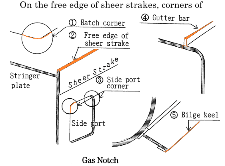
On the free edge of sheer strakes, corners of hatch openings in 0.6 L amidships, corners of side ports, free edges of gutter bars and bilge keels, any gas notches are unacceptable. Big notches are to be filled by welding avoiding the short bead and then smoothened with a grinder. The allowable notch size on free edges other than the above is 1.0 ㎜ or less.
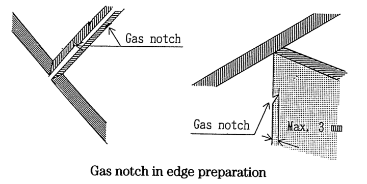
Notches in welding edge preparation
The allowable depth of gas notches in edge preparation before welding is as follows :
(1) 0.6 L midship area 2mm or less
(2) Others 3mm or less
(3) Fillet weld 3mm or less
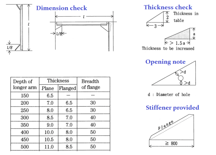
Accuracy of flanged members
When the brackets and/or flanged longitudinal members are used, the sampling measurement of flanged members is to be carried out under the following standard range and tolerance limits.

Line heat bending
Mild steel and ordinary high tensile steel
The standard procedure in the line heat ending
Method of mild steel plate and normal high tensile steel plate is such that when the maximum heating temperature is approximately 650 ℃ the plates may be subjected to immediate water cooling, but if such temperature ranges from 700 ℃ to 900 ℃ , they must be either air cooled or they should be allowed to cool down to about 500 ℃ and then be water cooled. For temperature control, thermo chalk is used.

For High tensile and TMCP high tensile steel:
a. 50 HT and TMCP type 50 HT steel (carbon equivalent Ceq > 0.38%)
1) Water cooling just after heating under 650 ℃
2) Air cooling after heating under 900 ℃
3) Air cooling and subsequent water cooling after heating under 900 ℃
starting temperature of water cooling to be under 500 ℃
b. TMCP type 50 HT A~D grade steel (carbon equivalent Ceq ≦ 0.38%)
Water cooling just after heating or air cooling under 1,000 ℃
c. TMCP type 50 HT E grade steel (carbon equivalent ℃ ≦ 0.38%)
Water cooling just after heating or air cooling under 900 ℃
Brackets
Brackets are fitted at the end of sections such as frames, beams and stiffeners. The Rule requirements for brackets are as follows :
Built-up section
Various section bars such as angles, bulb plates, pipes etc. from the steel mill are of standard size. If the shipyard wants special section bars, they must be fabricated at the shipyard or by sub-contractors.
In general, a symmetrical T section is used as the bottom longitudinal frame and deck longitudinal beam. But in order to avoid the accumulation of sludge or grain cargo on web plates, an L section is adopted as a side longitudinal frame.

But as the results of stress analysis show, an asymmetrical L section causes higher stress on the face plate and recently the use of a T section as a side longitudinal frame for large ships has been reconsidered.

Fitting accuracy and flawed welding
For allowable error in respect of assembly accuracy, both the standards and the shipyard’s standards may be referred to depending on the actual situations encountered.
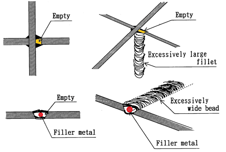
For areas where all welding work has been completed, inspection for mismatches and superficial gaps should be carried out as well as for the fore-mentioned standards. Superficial gaps at the welding joints may be ascertained even after the completion of
welding. Sometimes flawed welding is hidden in excessively wide beads as shown above.

3 thoughts on “HULL SURVEY: FABRICATION & ASSEMBLY PROCEDURE”