

Ball valve at first glance:


Some time we will see arrow on body of ball valve. Does it show flow direction?
Related topics:
+ Check valve : Flow direction of Valve – Part 1 (CHECK VALVE)
+ Ball valve: Flow direction of Valve – Part 2 (BALL VALVE)
+ Globe valve: Flow direction of Valve – Part 3 ( Globe valve ) and Flow direction of Valve – Part 4 (GLOBE VALVE) continue
+ Butterfly valve: Flow direction of Valve – Part 5 (BUTTERFLY VALVE)
- Flow direction of conventional ball valves: Bidirectional:
– As a rule of thumb, the flow direction of ball valves, no matter it is designed to floating type or trunnion mounted, shall be bidirectional. In the conventional design, two identical round seats are fixed or floating on the upstream and downstream side of the ball. The double-seated ball valve secures a bubble tight shut-off with moderate pressure drops and soft seating materials. Changing direction of the ball valve during installation shall not affect its sealing performance. See the sectional view of a bidirectional:
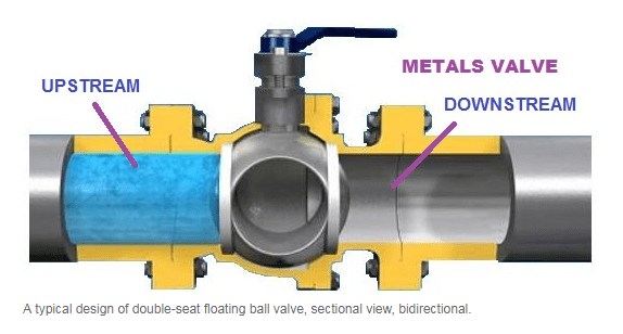
-
Unidirectional Ball Valves:
– However, in project practice, there are some ball valves marked with flow direction arrow on the surface.These ball valves only have one single flow direction and are called as “unidirectional”.
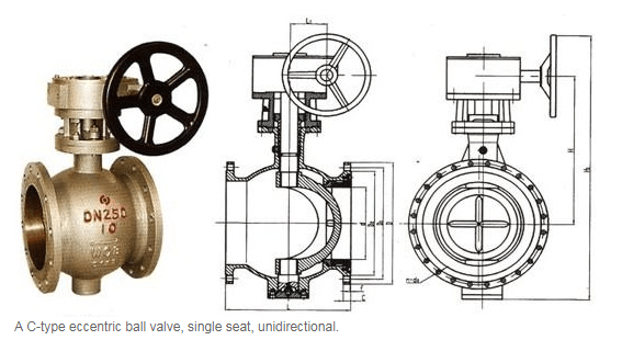
– The C ball valve, also known as eccentric ball valve or half ball valve, has a typical single seat design. The C-style half ball design eliminates cleaning dead spot as well as requires a unidirectional installation.

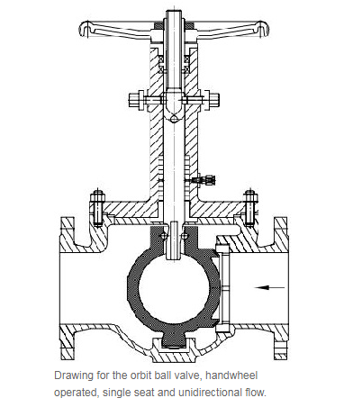
– Similar single-seat design is commonly seen in V port ball valves and orbit ball valves both of which limit the valve to unidirectional flow. Usually the single-seat end shall be connected with the upstream flow.
Have two notes as below to be take care:
- In term of the working conditions, some double-seats ball valves are also designed to single flow direction. Take cryogenic ball valves used for liquid chlorine and LNG application for example, there is always a pressure relief hole drilled in the ball on the upstream side. This bleeding hole is designed to vent the ball cavity in case the liquid gas vaporizes at an elevated temperature causing over-pressure problems. The cavity relief must be upstream hence it is unidirectional.
- A minor problem with some ball valves is the fluid trapped between the ball and the two seats when the valve is closed. As the liquid and valve expand and contract with temperature, differential expansion between them can cause pressures inside the valve to be high enough for the valve to leak. Higher-quality valves have a provision in their manufacture to minimise the possibility of this trapped fluid leaking, and for that reason they have an arrow cast into the valve body indicating the preferred direction of flow when the valve is open. It is best to follow this convention when installing these valves.
2. Special note for ball valve: An Aerodynamic Torque (for more information only):
- Static pressure: As fluid flows through a rotary control valve, static pressure does not act uniformly on the ball’s surface. This creates unbalanced forces causing additional torque on the closure element called ‘aerodynamic torque’ (Figure 1). For effective actuator sizing, aerodynamic torque must be considered as well as the friction torque. If omitted, it may have an undesirable change or interruption to the process, and eventually stall the actuator. This phenomenon is well recognized in the butterfly valve industry; however, it becomes more complex in control valve applications. In general, adding control trim to a ball valve alters the symmetric shape and significantly impacts its aerodynamic torque curve, making it difficult to predict.

- Dynamic torque study
It is investigated the impact of aerodynamic torque on an overall torque curve, with a goal to customize the torque curve to suit the user’s specific flow conditions. The modified torque curve will ensure accurate and reliable actuator sizing with potential reduction in overall actuator cost.In this study, computational fluid dynamics (CFD) combined with the well-recognized aerodynamic torque equation, Td = Ct D3 Y Δp, are used to predict the aerodynamic torque behaviors. Figure 2 shows how aerodynamic torque is caused by non-uniform static pressure distribution when fluid flows past the ball’s surface. It was found that a substantial difference in the aerodynamic torque coefficient (Ct) occurs depending on the control trim location. The seat trim configuration has the most favorable aerodynamic torque coefficient of all positions tested. More than 50% reduction in aerodynamic torque coefficient can be obtained by changing the trim location from inside the ball to the seat configuration (Figure 3).

Pls see next part:

7 thoughts on “Flow direction of Valve – Part 2 ( ball valve )”