

Related topics:
+ Check valve : Flow direction of Valve – Part 1 (CHECK VALVE)
+ Ball valve: Flow direction of Valve – Part 2 (BALL VALVE)
+ Globe valve: Flow direction of Valve – Part 3 ( Globe valve ) and Flow direction of Valve – Part 4 (GLOBE VALVE) continue
+ Butterfly valve: Flow direction of Valve – Part 5 (BUTTERFLY VALVE)
Solving cavitation in globe valves:
Cavitation, as a type of erosion, is known as the most important operational problem for globe valves. We have to looks at the causes of cavitation and suggests solutions to mitigate or avoid cavitation in manual globe valves.
Globe valves are often used for throttling, and the most common design is the T pattern body (Figure 1). However, the two 90° turns made by the flow before and after the plug plus the narrow flow path in the centre of the valve below the plug result in a substantial pressure drop. If the pressure in a liquid flow at the narrow area below the plug drops below the vapour pressure, bubbles of gas can vaporise from the liquid in a process called “flashing”. When these bubbles recover pressure they collapse firmly in a way that creates pressure waves. It is these pressure waves can cause damage to the seat, plug and body of the globe valves.

Per the Bernoulli principle, there is a massive shift from static pressure energy to kinetic energy; this high velocity flow condition causes destructive erosion of a valve’s internal surfaces, and other problems such as cavitation, flashing, noise, turbulence and vibration.

Cavitation consequences:
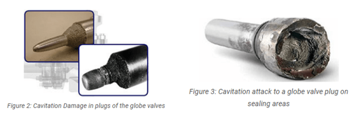
Cavitation can create irregular pits and erosion in the valve trim (seat and plug) and body as well as in downstream piping (Figure 2). Cavitation intensifies ( increase ) the effect of corrosion which could be called “Cavitation Corrosion”. Figure 3 shows a major cavitation attack in the form of pits on the plug sealing areas in a globe valve. Damage such as this will cause the valve to lose its sealing capability.
Cavitation can also produce excessive noise and vibration and create localized stresses (loads) on the valve bodies in addition to pitting corrosion and erosion. Vibration and noise reduce the globe valve’s efficiency and are therefore considered as the secondary concern of the cavitation after material damage.

Cavitation affected parameters:
Cavitation does not necessarily create damage. The extent of the cavitation damage depends on the following parameters:
- Pressure drop: Higher pressure drop increases the cavitation effect. T type globe valves are severely exposed to cavitation because of the high value of the pressure drop.
- Leakage: Leakage is the movement of the fluid from the high to the low pressure area. This pressure drop intensifies the cavitation risk especially when the valve is closed.
- Material: Harder materials are less vulnerable ( effect ) to the cavitation damage.
- Valve size: Cavitation could be more severe in the larger size valves.
- Trim design: “Anti-Cavitation” or “Multi Step” trim design reduces the cavitation effect.

- Flow regime: Turbulent ( complex ) and high velocity flow increases the risk of erosion and cavitation.
Cavitation reduction solutions:
- Anti cavitation trim: with a multi step trim design the pressure decreases in two or more stages thus avoiding a high pressure drop in a single stage.
- Hard trim materials: Hard trim materials like Stellite 6 (UNS R30006) or Stellite 21 as a form of solid or overlay and 13Cr martensitic stainless steels like UNS S41000 or 415000 have higher resistance against cavitation.
- New globe valves standard: American Petroleum Standard (API) has released the first edition of the new globe valve design standard (API 623) to control and avoid operation problems in globe valves like cavitation, vibration and leakage.
- Alternative valve selection: More costly Y-Pattern globe valves or axial on off / control valves are good alternatives for traditional T-Type globe valves.

5 thoughts on “Flow direction of Valve – Part 4 ( Globe valve ) cont’”